int sensorPin = A0; // select the input pin for the potentiometer
int ledPin = 13; // select the pin for the LED
int sensorValue = 0; // variable to store the value coming from the sensor
void setup() {
// declare the ledPin as an OUTPUT:
pinMode(ledPin, OUTPUT);
}
void loop() {
// read the value from the sensor:
sensorValue = analogRead(sensorPin);
// turn the ledPin on
digitalWrite(ledPin, HIGH);
// stop the program for <sensorValue> milliseconds:
// NEW VARIATION: stop the program for <sensorValue> milliseconds / 2
delay(sensorValue / 2);
// turn the ledPin off:
digitalWrite(ledPin, LOW);
// stop the program for for <sensorValue> milliseconds:
delay(sensorValue);
}
Monday, May 23, 2016
Question 18.1 - Resistors

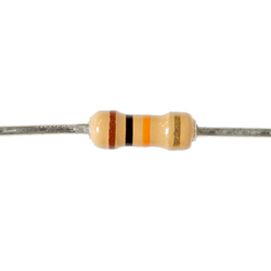 |
| 1 x 10 k ohm resistance, +-5% Tolerance |
 |
| 330 * 1 ohm resistance, +-5% Tolerance |
Friday, May 6, 2016
Wearable Project - the Tw(h)at
Arduino
Wearable Project. Title: Tw(h)at
Oscar
Macdonald
The Project:
A sturdy, rigid
hat is equipped with an Arduino and a 5V power bank. The Arduino uses a
temperature sensor (TMP36) and DC motor fan, directed at the face of the wearer.
The motor fan changes speed (between 0 and 255 using pulse-width modulation)
depending on the temperature detected, and is mapped between 15 and 25 degrees
Celsius. In short the fan will spin faster as the temperature increases, reaching
a maximum speed of 255 at 25 degrees or higher, and will spin slower as the
temperature decreases, completely stopping at 15 degrees or lower. The Arduino
can also connect to a computer with the Arduino IDE installed and output the
temperature on a serial connection at 9600 baud.
 |
| Finished project |
 |
| Fritzing diagram |
 |
| Schematic |
In the above
video, the temperature sensor is using the room temperature (~19 degrees at time
of recording) and altering the speed of the motor. The Tw(h)at has it's own mobile power supply and is ready to be worn.
C Code:
/* Code written
by Oscar Macdonald
*
* Code adapted from SIK giude sketch #7:
Temperature Sensor and #12: Spinning a Motor
*
* Credit to Peter Brook
*
* 05/05/2016
*
* This arduino sketch uses a TMP36 temperature
sensor to detect temperature
* (in voltage) and send the information to the
Arduino. The Arduino converts
* the voltage to Celsius, sends the
temperature across a serial line to be
* monitored by the Arduino IDE (for testing
purposes) and maps the temperature
* between 0 and 255. The mapped value is sent
to a DC motor.If the temperature
* is above 15deg, the fan will begin to spin,
reaching a maximum speed at 25deg.
*/
const int
temperaturePin = 0; //pin input for temperature sensor
const int
motorPin = 9; //pin output for DC
motor
int speed; //speed value sent out
motorPin
void setup() {
Serial.begin(9600); //bps to connect to Arduino IDE serial
monitor
pinMode(motorPin, OUTPUT); //set motorPin as an output pin
}
void loop() {
float voltage, degreesC; //values for voltage from temperature
sensor, and temperature in Celsius
voltage = getVoltage(temperaturePin);
degreesC = (voltage - 0.5) * 100.0;
//converts voltage into degrees
Serial.println(degreesC); // output temperature to serial
monitor
speed = map(degreesC, 15, 25, 0, 255); //map the temperature between 15 and 25
degrees
analogWrite(motorPin, speed); //send the new mapped speed to the
motor
}
float
getVoltage(int temperaturePin)
{
return (analogRead(temperaturePin) *
0.004882814);
// This equation converts the 0 to 1023 value
that analogRead()
// returns, into a 0.0 to 5.0 value that is
the true voltage
// being read at that pin.
}
Reflection
The idea for the
Tw(h)at was inspired by the SIK Guide Circuit #12: Spinning a DC Motor. I had
previously completed Circuit #7: Temperature Sensor, and it was easy to
integrate the two circuits into a single, applicable design.
I learnt how to
use the map function in SIK Guide circuit #9, which uses a servo instead of a
motor. The map function is almost essential to my design and saves a lot of time
spent coding the function myself. Originally I mapped the temperature to 15 and
35 degrees, but it was difficult to see the change in the motor speed. I
decided to map the temperature to 15 and 25 degrees instead, which would show
the change in speed better and would be more comfortable for the wearer.
After achieving a
working model, the next step was to attach the complete circuit to a hat. The
hat must be sturdy and have a brim wide enough to attach the fan and taught
enough to support the weight. The hat also needs to have a sturdy top so the Arduino
and circuit board can sit on it without moving. The final requirement for the
Tw(h)at is a power supply; either a pair of 5V batteries or a 5V power bank. I
chose the power bank to avoid unrecyclable batter usage. To keep the components
secure to the hat, cable ties are used to secure them in place without damaging
them. Other fixtures include adhesive tape, glue, or screws. Each of these
would be a poor fixture as they were unreliable and/or could damage the
components.
The current
design does not have an actual fan attached to the DC motor, and the DC motor
is not attached to the brim of the hat, but the fundamentals of the project are
in place and are in working order. I believe that while the Tw(h)at would have
very few buyers if it were ever put on the market, it is still a simple and
neat idea. If I did this project again, I would minimize the components to a
single box that could be attached to the brim of the hat, using a single chip
with all required components, including ATmega328p, transistor, and temp sensor
attached to it.
References:
Subscribe to:
Comments (Atom)